Canon Science Lab
Digital Copying Machines
Digital copying machines are capable of scanning text and images to create digital data, and printing documents. Various mechanisms within copying machines make use of optical and lens technologies.
In offices today, digital multifunction systems have become the norm. In addition to copying, these machines offer faxing, printing and scanning functions, but the mechanics are the same as those used in digital copying machines.
A digital copying machine is made up of an input unit (scanner) for reading documents as digital data, a laser unit that uses laser light to form images based on the scanned data, and an output unit (printer) for printing the image formed. The input unit utilizes LEDs and a CCD sensor, and the basic principles and mechanisms are the same as those used in standalone scanners. Laser light is used in the laser unit and output unit. The basic principles and mechanisms in the laser unit and output unit are similar to those used in a laser printer.
Two Types of Scanner Mechanism
Scanners for reading documents make use of either a CCD sensor or a CIS (Contact Image Sensor).
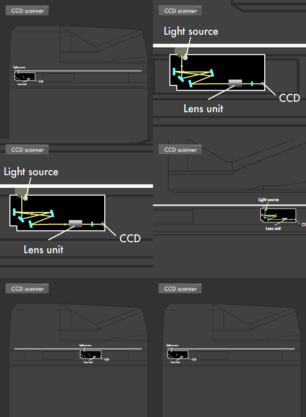
The CCD sensor reads documents one line at a time from the bottom, converting a white LED point light source into a linear light source. The line-shaped LED light, reflected by multiple mirrors, is guided to the lens unit to ensure a fixed light path length (distance of the path traveled by the light). Aberration correction is performed on the light in the lens unit, and a reduced projection is made on the imaging element (CCD sensor line sensor) to create digital data.
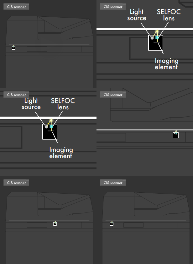
In the CIS format, three LEDs in the RGB primary colors are used as the light source. The LED, lens array, CCD sensor and CMOS line sensor are aligned with the same width as the scanner bed, and each pixel is read 1:1. This is called the Contact Image Sensor format for reading a document by being in contact with it. As there is no need to secure the light path length, the mechanism can be made relatively compact.


Unit Controlling Laser Light
Image data read by the scanner is formed as an image on a photosensitive drum in the printer mechanism using laser light.
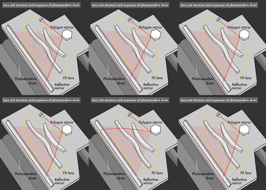
The image data is converted into laser light ON/OFF information by the controller, and sent to the laser unit. The laser light emitted by the laser oscillator in the laser unit is focused by passing through a lens and reflected by a polygon mirror.
A polygon mirror is a mirror with four to six faces, which rotates quickly (at 20,000-40,000 rpm). While rotating, pixels for a single mirror face draw (scan) a single horizontal line (several lines in some models) on the photosensitive drum. For example, when scanning one line per face, six lines are scanned for each revolution if the mirror has six faces.

During this time, if even the slightest angle error (slant) should occur on any of the polygon mirror faces, the path of the laser light would change (optical face tangle), preventing accurate image formation.
To ensure accurate image formation, a lens unit called an Fθ lens is used between the polygon mirror and the reflective mirror irradiating the photosensitive drum with laser light. The Fθ lens serves two functions: scanning laser light onto the photosensitive drum at a uniform speed, and accurately irradiating the photosensitive drum with laser light, even in the event of optical face tangle occurring on the polygon mirror. This Fθ lens enables pinpoint accuracy when irradiating the photosensitive drum with laser light.
Printing Processes Using Laser Light and Static Electricity
The photosensitive drum in the printer mechanism uses a material called a photoconductor, which acts as an insulator in the dark, and as a conductor when in contact with light.
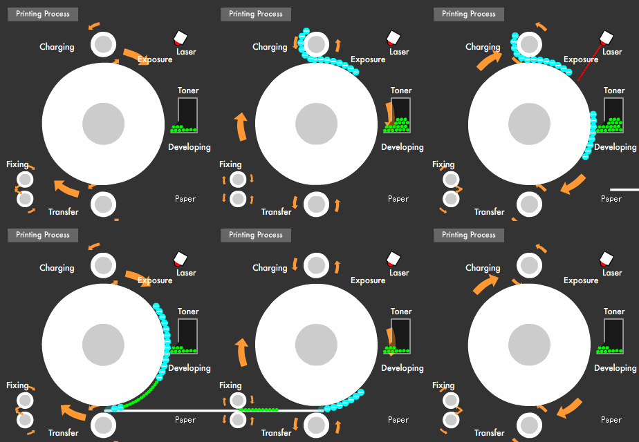
The surface of the photosensitive drum is charged with static electricity of around -700 volts (electrostatic charge) to give it a negative charge. In areas irradiated by laser light that is ON, the photoconductor acts as a conductor and the charge is reduced (exposure). The areas not irradiated because the laser light is OFF retain their charge.
When negatively charged toner approaches the photosensitive drum, the toner attaches to parts that have lost their charge (developing). A reverse image is created by the partial attachment of toner to the photosensitive drum.

Paper is brought into contact with the photosensitive drum and toner attaches to the paper when the reverse side of the paper is given a positive charge (transfer). Printing is complete when the toner is fixed to the paper through the application of heat and pressure.
